
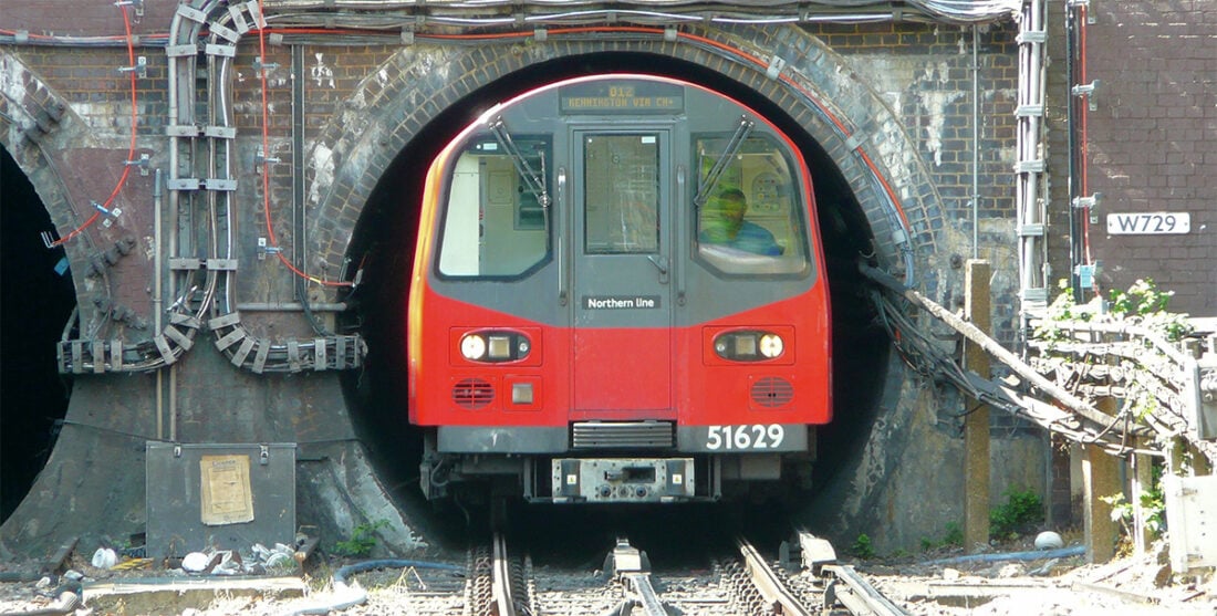
Railway design demands precision, leaving no room for error. Validating the dynamic kinematic envelope (DKE) and other railway clearances is a critical task. Traditional methods of clearance validation are laborious and can be prone to misinterpretation. The meticulous calculations required by engineers to ensure that safety standards are met have often been done in 2D static drawings and may be recast many times over during a design or operational management review. This makes detecting clashes and areas of non-compliance challenging, especially when planning track changes, railway slews, and new alignments, with significant time needed for recalculation whenever a proposed rail alignment or vehicle specification changes.
Here, we illustrate how a 3D CGI platform of complex railway environments allows the rapid identification of clearance conflicts between rolling stock and infrastructure, facilitating real-time certainty, enhancing safety, and dramatically reducing development and approval timeframes. Packed with examples from modern railway infrastructure projects, this article presents a comprehensive guide to the 3D simulation and visualisation of dynamic kinematic envelopes and other safety clearances within the railway industry.
CONTENTS: Loading gauge | What is a kinematic envelope? | Dynamic kinematic envelope | Measuring DKE | Structure gauge | Swept path | Other railway safety clearances | Kinematic envelope and clearance assessment | Track clearances | Train yard, station, and platform clearances | Tunnel and bridge clearances | Simulating the kinematic envelope | Benefits of CGI Digital Twins for clearance validation
Rail clearances and safety margins: a brief introduction
Railway clearances are the specific dimensions set out by transportation authorities to establish safe distances between trains and nearby obstructions. These clearances ensure adequate safety margins around vehicles, helping prevent collisions with surrounding infrastructure and rolling stock on adjacent tracks. Clearance management is a vitally important part of railway planning, directly impacting safety and risk.
Before we explore the advantages of railway simulation software and platforms in analysing these safety clearances, let us clarify a few key terms.
What is a loading gauge?
A ‘loading gauge’ in railway refers to the maximum physical size of a train and its load, including side mirrors and other protrusions. By measuring various points along the length of the train, the loading gauge for a specific vehicle model can be determined.
Loading gauges vary significantly between countries and railway systems. A ‘restricted loading gauge’ indicates dimensions that are smaller than the norm for a particular railway system. For example, the British Railway loading gauge is restricted in certain areas. The typical loading gauge in the UK is smaller in comparison to more modern or international standards because trains are required to fit within infrastructure built many years ago.
What is a kinematic envelope?
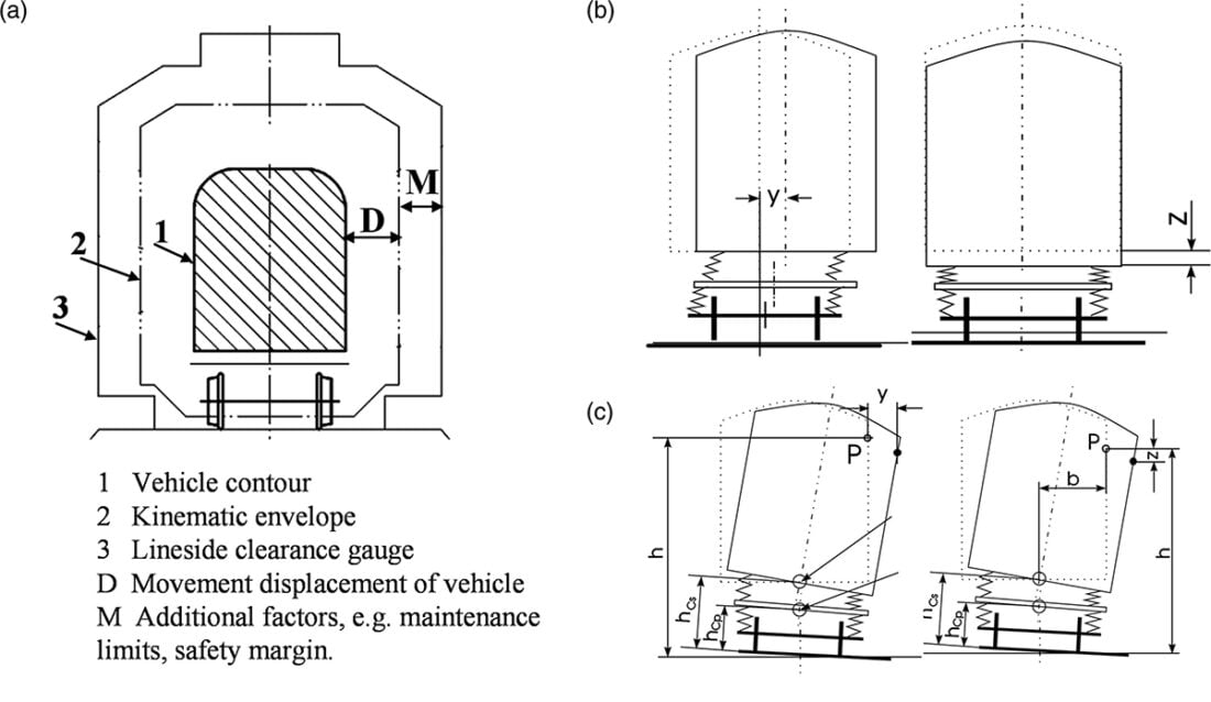
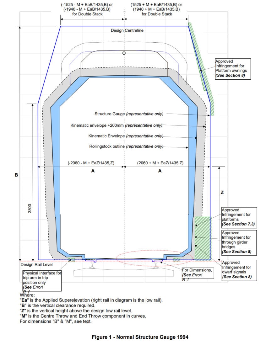
Where the loading gauge describes the outer dimensions of a stationary train, the kinematic envelope represents the largest volume that rolling stock can occupy as it travels along a railway track at speed. The kinematic envelope takes into account the expected movement of the train, including lateral swaying, vertical bouncing, and track cant around cornering. Because a kinematic envelope describes the motions of the train, it is larger than the loading gauge and represents the geometric limits or maximum anticipated displacement under legal operating conditions. Calculating the kinematic envelope is necessary to ensure safety and compatibility between vehicles and surrounding infrastructure.
The Australian Rail Track Corporation (ARTC) provides the following definition of the kinematic envelope:
“The area representing the maximum considered range of occupancy of the rollingstock, taking into account all track and rollingstock movement tolerances.”
– Australian Rail Track Corporation (ARTC), Technical Note – Operational Infringement Waivers, Track and Civil Code of Practice – Section 7 Clearances (2022)[i]
The Dynamic Kinematic Envelope (DKE)
A dynamic kinematic envelope (sometimes referred to as a developed kinematic envelope) considers extreme or unusual movements of a train, which may occur under less predictable circumstances, covering a wider range of possible motions. This can include additional sway or tilt due to high winds, larger-than-usual bouncing due to track irregularities, or extended overhang when the train moves at high speed through tight curves. The dynamic kinematic envelope represents the outer limits that rolling stock is predicted to occupy given worst-case conditions.
Winds and environmental conditions can play a considerable factor in rail car movements, to the point where tragedy can occur if rail cars are blown off tracks in high-speed winds, such as when 800 people died in India in June 1981 when seven rear coaches of a passenger train were blown off track by the wind and plunged into a river during a cyclone.
“Dynamic” accounts for changes that occur when the train is subjected to forces such as those caused by speed or wind during operation, resulting in tilting, swaying, or overhang on curves. “Kinematic” references the motion of the train, encompassing factors such as speed and direction. An “envelope” in this context refers to the outer boundaries or limits of the three-dimensional space that the train is predicted to occupy. A dynamic kinematic envelope therefore embodies the maximum real-world dynamic movement of the train.
How is the kinematic envelope measured?
Kinematic envelope measurement is considerably more complex than that of the loading gauge, as it requires anticipation of the train’s movement while subjected to dynamic fluctuating forces.
“The evaluation of the relative motion between the carbodies in a train involves some of the most complex issues of railway dynamics. Assuming that the flexibility of each carshell does not play any role in the behavior of the trainset, a train can be viewed as a collection of a rigid bodies connected by rigid or flexible links, supported by mechanical systems known as bogies, which include the wheelsets that are the sub-systems ultimately in contact with the railway.”
– Jorge Ambrósio, Train kinematics for the design of railway vehicle components (2010)[iii]
Kinematic envelope calculations vary depending on the specific regulations, rules, and criteria in different countries and regions. However, the process typically involves consideration of several parameters, such as:
- Static vehicle dimensions: The structure gauge profile – clearance height, width, and length – forms the basis of the calculation.
- Suspension system: A suspension system that absorbs shock and vibrations from the track can significantly influence a train’s predicted bounce and sway. For example, a train with a softer suspension system would likely have increased vertical movement while travelling over bumps or uneven tracks, resulting in a larger kinematic envelope. The suspension mode can hence factor into the kinematic envelope calculation.
- Roll, tilt, and sway testing results: Conventional trains maintain an upright orientation irrespective of the track’s curves, whereas tilting trains are designed to lean into curves to sustain higher speeds without causing discomfort to passengers. These trains thus have a different kinematic envelope.
- Curve overthrow: The overhang of vehicles while travelling around curves is affected by the sharpness of the curves, length of nose and tail overhangs, as well as the shape and size of the train. Overthrows at both ends of the train – centre and end throw – are considered in this assessment.
- Wind speed and other weather effects: High wind environments can increase swaying and tilting, necessitating additional clearance for safe operation.
- Variations in superelevation: Superelevation (also known as ‘cant’) is the practice of raising one rail higher than the other on a curve and angling the tracks. This counteracts the centrifugal forces that might otherwise compromise the safe and comfortable negotiation of corners by the train. Clearances are typically applied in alignment with the plane of the superelevation. ‘Crosslevel’ refers to the difference in elevation between the two rails.
- Track speed limits: Increased velocity creates a larger kinematic envelope due to increased sway; therefore, track speed limits impact the dynamic kinematic envelope.
- Track geometry: The alignment of straight sections and curves, gradients/inclines, and the distance between rails (known as the ‘track gauge’) significantly influence the kinematic envelope.
- Load throw: This refers to the potential for cargo to shift or move significantly due to various factors such as uneven loading, track vibrations, braking momentum, or centrifugal forces while traversing corners.
- Track quality, tolerances, and wear: These factors include the condition of the track, maintenance tolerances, and ‘fixity’ (the tendency for the track to shift with time or move laterally), which is partly dependent upon the age and construction type of the railway.
- Vehicle tolerances: Deviations and small margins of error in manufacturing, construction, and maintenance processes impact the level of certainty in kinematic envelope calculations.
The kinematic envelope calculation may include some or many of these factors. While specifics of the calculation vary, the ultimate objective remains the same: to ensure the safe transit of trains without risk of collision or derailment.

What is a structure gauge?
Whereas the loading gauge refers to the outer perimeter of the loaded train, and a kinematic envelope represents the train in motion, a railway structure gauge defines the constraints imposed by the railway infrastructure itself.
Sometimes referred to as a ‘construction gauge,’ ‘minimum clearance outline,’ or ‘absolute gauge,’ this is the cross-sectional boundary representing the limits of the railway infrastructure (including wiring, electrical equipment boxes, cables, signal posts, and so on), ensuring an unobstructed path for the oncoming train. The structure gauge defines the available space within a particular railway line and determines the size of trains that can operate safely on a track.
The key difference between a loading gauge and a construction gauge or structure gauge is that the former refers to the size of the train and its load, whereas the latter refers to the size of the infrastructure – such as the inner dimensions of tunnel entrances. For obvious reasons, the structure gauge envelope must be larger than the train envelope, with adequate clearances, safety margins, and tolerances between.

What is the swept path?
The ‘swept path’ refers to a two-dimensional projection of a train’s kinematic envelope onto the rail corridor floor – a footprint of the train’s movement as it traverses the railway line. The swept path traces the extreme lateral movements of the train, tracking all dynamic behaviours caused by speed, load, and track conditions.
Swept path assessment primarily focuses on the horizontal dimensions, including the maximum overhang and sway of train components as the train moves around corners and progresses along the track. As such, it represents a path along the ground, mirroring the train’s trajectory.
Establishing the swept path often requires dynamic simulations using vehicle-swept path analysis software. As with all clearance requirements, undertaking swept path analysis by hand is tedious and involves time-consuming calculations. Using real-time CGI technology with physics acceleration to calculate and simulate these swept paths for analysis can make processes much more efficient.

Other railway safety clearances
Another area where safety envelopes prove invaluable is in modelling the safe clearance from overhead power lines and overhead line equipment (OLE). The OLE system, which delivers high-voltage electricity to trains, demands the enforcement of strict safety protocols. Advanced CGI technology can simulate safety zones around the OLE, enabling precise evaluation of overhead line clearance and potential hazards during operation and maintenance.


Kinematic envelope and railway clearance assessment
Engineers are required to calculate the dimensions of various railroad clearance envelopes and evaluate the interactions and relationships between these. Railroad track clearance requirements demand adequate spacing between adjacent rail lines, as well as between trains and tunnels, bridges, retaining walls, platforms, electrical infrastructure, signalling equipment, and so on.
Clearance assessments are essential in rail alignment and line planning and are particularly critical when introducing new rolling stock or planning upgrades and new developments.

Track clearances
Assessment of track clearances typically involves rigorous theoretical analysis complemented by physical gauge clearance. This physical assessment is carried out by a ‘structure gauging train’ – a specialised train equipped with various sensors and measuring devices, including lasers and cameras. The gauging train identifies encroaching objects such as gantries, overhanging wiring, eroding rock faces, or protruding tree growth, pinpointing where remedial work or maintenance is required.
In addition to ordinary clearances, the rail corridor must include refuge spaces for crew to move into if trains pass while maintenance is carried out. These refuges may require clearances of several metres.

Train yard, station, and railway platform clearances
Clearances around train yards, stations, and railway platforms must balance many interrelated factors, such as the relationship between the kinematic envelope and other tracks, the distance between tracks to buildings, and head clearance for platform canopies and other elevated structures.
Platform clearance involves careful consideration of the interface between the platform edge and the train, the height of the platform relative to the train floor, emergency exit and door clearances, and the provision of safe boarding and cargo loading areas.

Incompatibility issues can arise when trains with different loading gauges use the same platform. For example, certain tracks may be authorised for use by ‘out of gauge load outline’ trains, impacting the clearance requirements for platforms adjacent to these tracks. Train yards can also employ electronic detectors to prevent wagons with loads exceeding permitted levels from exiting the facility or to prevent trains with a larger loading gauge from inadvertently entering a restricted gauge line. The length of the train is also a factor. For instance, if a long train stops beside a curving platform, unsafe gaps may occur.
When employees work close to operational trains, additional service space beyond the kinematic envelope is necessary – as with the refuge space for maintenance purposes. All these factors can be effectively evaluated together within a 3D digital model.


Tunnel, overpass, and railroad bridge clearance
Over time, the railway industry has steadily shifted towards larger and more standardised loading gauges. To accommodate these changes – as well as to accommodate electrification – many rail lines have undergone extensive upgrades, including elevating bridges and augmenting tunnel heights.
Due to their enclosed nature, tunnels require sufficient height clearances between the top of tracks and the underside of structural members. These clearances must include provisions for the avoidance of brackets and electrical wires. Heat dissipation and aerodynamics also come into play, requiring sufficient space for proper ventilation, minimising air resistance as trains pass through the tunnel.
Railway bridges also have special clearance requirements, such as the positioning of derailment curbs, which must extend above the adjacent rail a sufficient distance to hinder derailment but not so far as to infringe upon the kinematic envelope.
Particular care must be taken to ensure that long tunnels and bridges have safe working spaces for maintenance staff, with clearance beyond the kinematic envelope. These refuges should be strategically placed at specific intervals along the length of the tunnel or bridge.
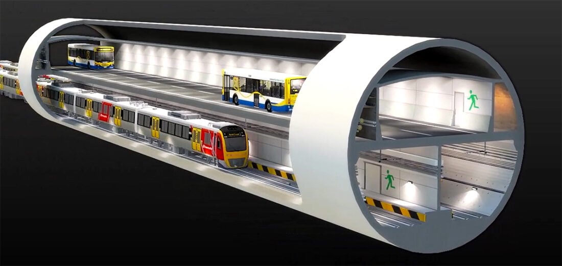
Long railway tunnels, especially those with twin-bore design (two parallel tunnels serving each direction), may also require cross passages at regular intervals for emergency access and evacuation. The design of these cross passages incorporates several safety clearances, ensuring there is sufficient height and width to accommodate the safe evacuation of passengers and provide sufficient space for emergency personnel and their equipment if required.

How digital simulations simplify kinematic envelope calculations and clearance assessments
Compliance validation involves the complicated interplay of many variables, including diverse vehicle class types, track alignment, and environmental conditions, assessed against regulatory rules and client specifications. Digital technology makes this process much easier.
“In fact, it was only really with the advent of desktop computing that we moved beyond paper calculations and started analysing vehicles dynamically, i.e. incorporating the effects of movement.”
– Gareth Dennis, Rail Engineer (2019)[v]
Unfortunately, most of the existing clearance validation software in the market remains frustratingly difficult to use, often requiring steep learning curves and considerable manual oversight.
Recent developments in state-of-the-art CGI technology, however, have revolutionised this field. Real-time physics-enabled simulation now allows for the precise modelling of rail routes, including dynamic kinematic envelopes and other safety clearances. This allows engineers to conduct comprehensive clearance assessments and a route risk analysis (RRA) within a realistic virtual 3D environment.
The impact of these advancements has been so profound that regulatory boards now sometimes explicitly require simulations instead of formulas for evaluating specific railway clearances.
“Section 13.3.2.4 – Removal of simplified formulae for calculation of clearances to platforms in transitioned track – replacement with requirement to use 3D modelling.”
– Technical Note TN 005: 2019, Transport Asset Standards Authority, NSW Government (2019)[iv] (emphasis added)
How Urban CGI Digital Twins technology can help

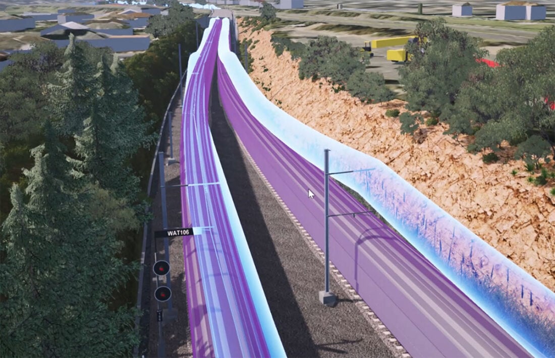
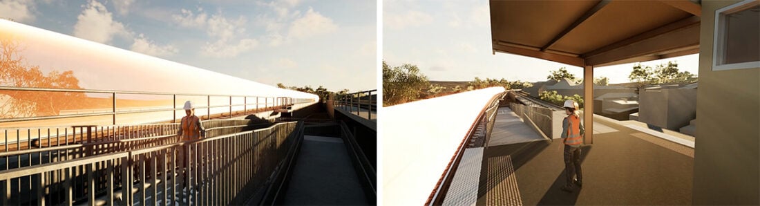
Our CGI Digital Twins technology creates accurate three-dimensional models of the dynamic kinematic envelope of rolling stock within a given rail environment. The DKE can be generated from the vehicle model cross-section supplied by engineers, or we can build a parametric version with an added physics layer as required, modelling how the train will behave under multiple conditions.
Once track data and train specifications are provided for in our system, the kinematic envelope is generated along the fixed path centreline and track spline as the rolling stock moves through the simulation. Similarly, the clearances and parameters for OLEs, gauges, infrastructure, track, egresses, and safety zones are all simulated and included on a case-by-case basis. As a physics-accelerated platform, dynamic collisions and alerts can be programmed into the system to provide physical constraints and highlights when collisions occur. The system can be built with standard survey data including LiDAR or photogrammetry and/or combined with modelled data including BIM, CAD, GIS and other geometrical design and construction models. We provide comprehensive support across the process, including advice and services for inputs, data, modelling, simulation and facilitation.
Urban CGI simplifies the process of planning and managing complex railway projects, including clearance planning and approvals. Our easy-to-use real-time CGI platform generates precise, high-resolution 3D simulated models of tunnel clearances, platform clearances, kinematic envelopes, safety envelopes for overhead lines, encroachment of vegetation, and other components and structures within the rail corridor. We can help you model and simulate rolling stock on adjacent tracks, test the feasibility of a new track layout, and verify new vehicle clearance on existing lines.
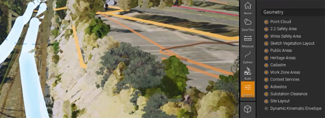
Caption: We have developed numerous custom safety envelopes tailed to the specific requirements of our railway clients. You can see from the menu on the left that our rail software can toggle on and off various static and dynamic clearance envelopes, such as the dynamic kinematic envelope, electric wire safety areas, safe work zone areas, and substation clearance zones. Other clearance envelopes can be added as custom features if required.
Our platform is continually updated in partnership with clients and through our own R&D, so you can access the latest technologies and innovations.
Benefits of our CGI Digital Twins railroad software and platform for clearance validation
- Faster identification of infringements and generation of solutions: With an intuitive and user-friendly interface, our platform makes it far easier to identify, assess and resolve clearance infringements. We can also build non-conformance feedback points to identify clashes and encroachments within the simulation. The 3D environment provides immediate clarity, allowing the review team to understand how the rolling stock will interact with a rail environment, quickly identifying clearance fouls. Clients can simulate a train’s movement, analyse the effects of proposed alignments and test feasibility in real time. This allows designers and engineers to quickly visualise the effects of geometry, including inswing and outswing as the train negotiates corners, ensuring trains maintain safe distances between other rolling stock and nearby infrastructure.
- Agile and flexible design refinement: Our software allows issues to be easily understood, negotiated and resolved. The immediate and in-depth visibility of changes within the simulation fosters rapid assessment of the impact of different design permutations and alignment options. This empowers engineers and designers to dedicate more time to optimising the design, eliminating poor designs quicker, and delivering substantially more value to the project.
- Accelerated compliance timelines: Our kinematic envelope simulations significantly reduce the number of design iterations required to achieve consensus. Clients tell us that clearance analysis and design development, which previously took weeks or even months, can now be accomplished within days, dramatically reducing approval timeframes.
- Safer and more efficient railway operations: The primary advantage of our kinematic envelope and clearance zone simulation is the improved safety this offers. 3D visualisation removes the guesswork from clearance analysis, leading to more informed and precise decision-making. The outcome is better space utilisation, safer railways, improved track layout, and enhanced rail alignment, optimising performance across the entire network.
- Enhanced comprehension, collaboration, and decision-making: Our solution facilitates a comprehensive understanding of complex scenarios and encourages stakeholders to align on clearance-related issues. By viewing 3D rail environments from all angles and viewpoints within an animated simulation, all parties gain immediate clarity, reducing uncertainties and fostering increased confidence in decision-making.
- Greater return on investment: Identifying potential clearance issues in a virtual 3D environment helps to avoid real-world collisions, costly modifications, and repairs. Furthermore, accelerating the planning process leads to substantial time and cost savings. In short, our CGI Digital Twins software transforms kinematic envelope validation and clearance assessment from a laborious undertaking to a powerful, agile, cost-efficient process.
The Urban CGI team will immerse ourselves in your project, aligning with your strategic goals. We provide a comprehensive end-to-end service, including the organisation of clearance assessment meetings and the facilitation of workshops between stakeholders as required.
We have decades of experience working with railway clients and extensive expertise in modelling rolling stock clearances, including the dynamic kinematic envelope and other safety zones. If you would like to learn more, please reach out and let us know your specific requirements. We will be in touch with more information about how we can assist!
REFERENCES
[i] Australian Rail Track Corporation (ARTC), Technical Note – Operational Infringement Waivers, Track and Civil Code of Practice – Section 7 Clearances, (2022)
[ii] Wenlin Shen, Huanyun Dai, Jing Zeng, Lai Wei, and Ren Luo, Calculation and testing approaches of the kinematic envelope for suspended monorail vehicles (2023)
[iii] Jorge Ambrósio, Train kinematics for the design of railway vehicle components (2010)
[iv] Technical Note – TN 005: 2019, Transport Assets Standard Authority, NSW Government, Australia (2019)
[v] Gareth Dennis, Rail Engineer (2019)
[vi] Rolling Stock Outlines, AS 7507:2017, Rail Industry Safety and Standards Board, Australian Standard (2017)


